555 Timer Schematics and Math
Written 2011-10-12
Tags:Remote Shutter Camera time-lapse Remote transistor Canon
.
This is a followup on building a time-lapse shutter controller, now that I have time to draw schematics and write math
There are several stages to the design:
- Power Supply
- Power Usage
- Frequency Range
- Output Coupling
Power Supply
I wanted to drive the device with AA batteries, but since the 555 timer I used requires a minimum of 4.5 volts and maximum of 15, that would require four rechargeable AA batteries. Instead I decided to go with a 9-volt cell, as a single battery can drive the circuit until it is nearly empty. However, this does have implications for the rest of the circuit. In particular, the output stage must accept being driven by voltage in the range of 8 to 3 volts, as the 555 may differ between 1.5 and 2 volts from a high on the output pin to the input voltage, but if everything is designed to handle this, then I don't need to regulate the power supplyPower Usage
Since this circuit is driven by a transistor, there should be little power usage in the output stage, but the 555 timer can be designed to use too much power. To avoid this, I went with a higher-quality capacitor with lower leakage current, and large-valued potentiometers.Frequency Range
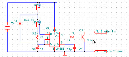
The frequency range and duty cycle are controlled by ratios of resistances to capacitance C2. The formula for time on is TimeOn = [C] * [R1] * ln(2). The formula for time off is usually TimeOff = [C2] * [R2] * ln(2), but also note that I added R3 in series with R2 so that the total resistance there can never drop below the speed my camera can take photos. My complete formula for off would be [C2] * ([R2]+[R3]) * ln(2). I would suggest picking a physically small, high quality(low leakage) capacitor, in the range at least 10uF, and the pick potentiometers to meet the range of timing you want to hit.Output Coupling
My circuit is tuned to efficiently drive my Canon 20d. Using a meter, the remote port was always about 10 milliamps shorted, and 3.3 volts open. Since the 555 outputs a voltage driven square wave, an NPN transistor can be added to convert a to a DC switch. I'd have to check the particular transistor used, but anything handling 15milliamps should do fine. Mine had a DC gain of 30->90, so I did all work assuming worst case hfe gain of 30. Keep in mind that the power supply section states a 4.5 volt supply is acceptable with 2.5 to 3 volts output from the 555. Also note that the NPN transistor will have some DC voltage drop over it, in my case 0.7 volts. The simplest method is to compute all calculations assuming smallest voltage to the 555, and pick the [R4] to match to ensure the transistor can trigger the camera, then go back and make sure the transistor can also deal with the current driven from the 555 when the 555 is fully powered and puts 8 volts out toward the transistor.Picking Parts
- 555 timer - there are several different kinds, including high power, high efficiency, rail-to-rail voltage output, and CMOS. Mine was nothing special, and I think any will do. You do not need a high-speed one for camera work
- Main capacitor C2 - this guy controls the range of frequencies the circuit will operate at. Also low-leakage is nice if you have it. Electrolytics can be sensitive to reverse voltage, so be careful about that
- On timing potentiometer R1 - this resistor controls the exposure time, so make sure to pick one, when combined with C2, that does what you need.
- Off timing potentiometer R2 - this resistor controls the time between exposures, so make sure to pick one, when combined with C2, that does what you need.
- 555 capacitor C1 - this is specific to your 555, and some list a range. 5pF to 22pF worked here for me, although 10pF was the 'ideal'. Some 555s do not need one.
- diode D1 - just a standard diode, this application is low voltage; almost any will do. This part allows you to run the exposure(on time) less than the off time.
- Transistor Q1 - most small signal NPN transistors will work. Needs to be able to sink the current from the camera remote port, which isn't much. I would pick higher gain over lower to try and save a little power, but I got mine out of a spare transistor bucket.
- DC Battery V1 - I added a 9-volt dry cell connector, but forgot a power switch
- power switch - not pictured, but do add this.
- optional LEDs - I added an LED driven from the 555 output so I could see the delay before shooting. Also could add power LED.