AntennaCraft Television Antenna Teardown
Written 2015-08-29
Tags:Teardown Analog Television Amplifier Antenna
A Short Story
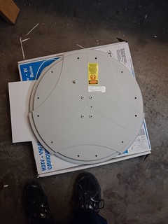
Several RadioShack stores were closing earlier this year. One store had paper tokens describing an antenna, on sale for about ten dollars, that could be purchased by taking the paper token to the cash register. After purchasing, the cashier would exchange the token for the antenna. Once the cashier returned from the back, I came to realize this antenna is massive, nearly two feet in diameter, and not something that would sit nicely behind my television. But, all sales are final at a store closing sale.
Packaging
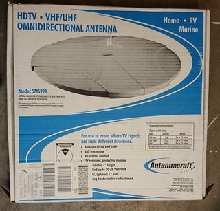
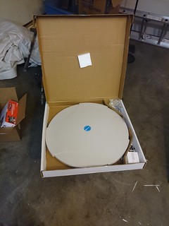
The antenna comes in a large, flat box. Inside you will find the antenna, a short run of 75 ohm coax, a DC wall adapter, and a power injector.
Inside the Antenna
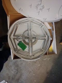
Twelve plastic-tapped screws hold the front and back of the antenna togther. Some of the screws also hold antenna elements together, which makes reassembly take a big of alignment. At this stage, removing the nut from the coax port is not required. The antenna elements almost appear to form a quad-helix, even though each elements is a bubble-lettered T.
RF Amplifier
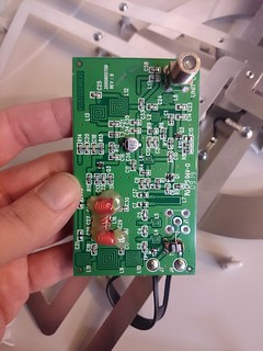
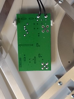
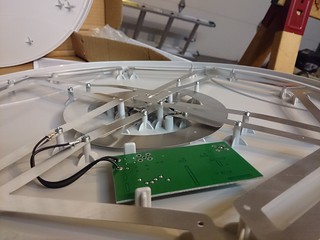
To remove the RF amplifier, the coax port nut most first be removed. This single PCB is responsible for wideband amplification. Power is supplied through the coax by a DC wall brick and power injector, runs the amplifier which pushes the boosted RF down the cable, and then past the power injector towards the television. Additionally, the unpopulated 5-pin port appears to support unbalanced coax to unbalanced coax amplification, although this configuration feeds in the balanced antenna directly.
