Caldwell Ballistic Precision Chronograph Theory of Operation and Signal Path
Written 2018-12-04
Tags:Chronograph Caldwell
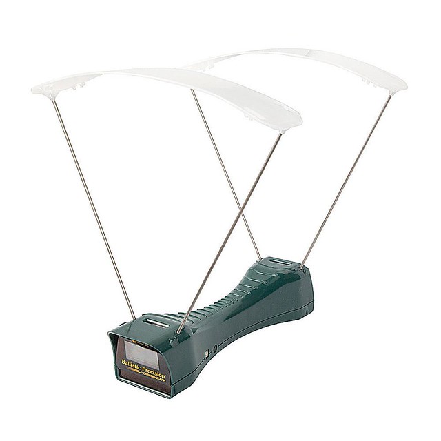
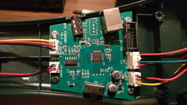
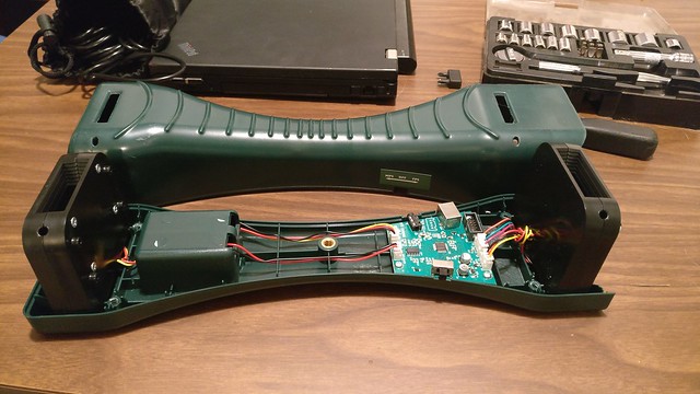
Inside my chronograph, we find this simple PCB. With only two chips and a handful of passive components, this device can measure speeds from 5 to nearly 10000 feet per second. Here is how it works. The chronograph waits for an object to pass the first light-gate, starts a timer, waits for the object to pass the second light gate, records the finish time, and divides the distance between light gates by the time, and converts to appropriate human-readable units for display.
PCB
Sensors
At each end of the device we see a large, black sensor module.
Sensor Amplifier
Connected to the sensors is a TI LM324 quad operational amplifier. This common component adds a lot of flexibility in the analog domain, but its general purpose is to amplify the signal coming from the sensors over a range of frequencies.Approach 1: Analog to Digital Converter - ADC
Connected to the output of the LM324 is the Silicon Labs C8051F380 microcontroller. From the datasheet we can see that the ADC is 10-bit resolution, up to 500kilosamples per second.
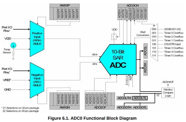
This is a pretty simple, basic ADC design. The window-compare feature may be used to allow the 8051 core to sleep while waiting for a signal pulse to arrive, but given that the chrono does nothing else, it may not be utilized. One nice thing about this ADC is that it features differential inputs. This means that instead of attempting to read the signals from both sensors we can instead subtract one from the other and feed it into the single ADC channel(this may also be done with the OpAmp).
I frankly have no idea what the signal of an arrow or bullet passing over a phototransistor when amplified by an unknown amplifier, but we can figure out some basic requirements from the device specifications, but we know a few thing:
- Approx 12 inches between light gates
- Claims to be accurate to within 0.25 percent
- Measures speeds from 5 to 9999fps
- 12 inches / 9999fps is approximately equal to 100us
- To be accurate to 0.25 percent, we need to be able to differentiate 100 and 100.25us
- To detect a 0.25us difference, we need a sample rate of 4MHz or higher
This is a problem, because the ADC can only run at 0.5MHz. What does that mean? With a sample-rate of 500kHz, we can work out the error over speed like so:
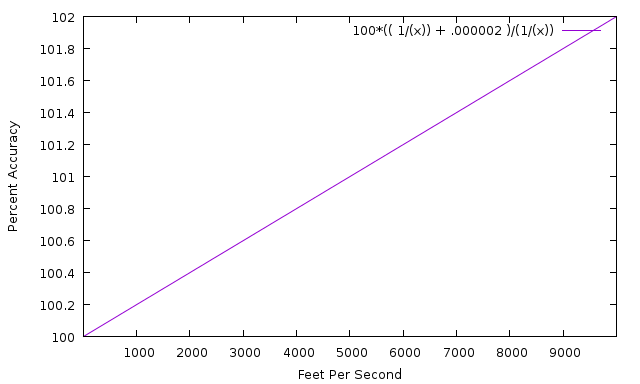
This means that either the device doesn't operate quite as it appears to, or Battenfeld Technologies / Caldwell cheated a little on their specifications. Not that anyone would notice - no bullet travels anywhere near 10000 feet per second, rare bullets travel approximately 5000 feet per second, but most are much, much lower than that. A 220 Swift might be 4000 feet per second, and the chrono would be around 0.8 percent accurate. Sadly, 0.25 percent accuracy is achieved only for 1000 feet per second and slower velocities. If the vendor is not fudging their specs, we can assume they are not using the ADC.
Approach 2: OpAmp as Digital Comparator
Assuming we use the quad-op-amp as two channels of amplifier-followed-by-hysteresis-controlled-op-amp, we can receive a digital pulse either with the two INT pins or using the GATE functionallity of the microcontroller timer unit, which enables counting only while a signal is high. With this configuration, the accuracy is limited by the speed and accuracy of the timer, which can run at up to 12MHz. Assuming 12MHz, and the same 100us vs 100.25us from above, a 12MHz timer can measure 100us, 100.083us, 100.167us, or 100.25us. Assuming the clock is accurate, this leads to an error of at most 0.09%, far better than the ADC-approach, and quite a bit better than the vendor's own estimate.
Other Error Sources
Clock Accuracy and Temperature
With any event-timer based system, the overall accuracy is goverened by the accuracy of the timer. Coincidentally, the C8051F380 main clock is only accurate to 0.25%. Given that the PCB does not have an external oscillator to enable high precision, the unit is limited to 0.25% accuracy, assuming there is no post-assembly calibration completed, which would have to be completed over the operating temperature range, and using the on-board temp sensor to calibrate it out.
Shot Alignment With Chronograph
All of the above discussion assumes the bullet takes the shortest path between the sensors. However, without rigidly mounting the gun barrel and chronograph together to something like a table, alignment will be sub-optimal. As the bullet path angle changes from straight through the chronograph, the path length changes with 1/cosine(angle). We can plot this error easily enough:
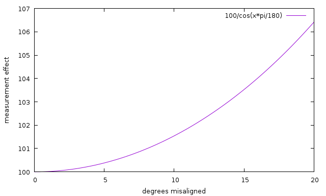
Although a 20 degree misalignment is pretty difficult to do by accident, it is easier to accumulate a 1% error at only 8 degrees of misalignment, and 4 degrees of misalignment add 0.25% error, as much as the chronograph has already. If you do not plan to rigidly mount the chrono and firearm, you are unlikely to achieve the published accuracy.