Repair and Reassembly of GW Instek GPD-3303S
Written 2026-11-09
Tags:Capacitor Repair PowerSupply
This summer, I had been using my lab bench to supply a flight controller. After several days up and a lightning storm, I noticed the LED display was flickering. Soon, relays were clicking and the output rails were cycling - not good. I pulled it apart, found two bulged capacitors, ordered replacements, and decided to take photos and notes when I reassembled it. I suppose disassembly is the reverse of reassembly.
Tools & Parts
I used:- 2x 2200uF, 16V capcitors. I used DigiKey 493-15470-ND
- Number 2 phillips screwdriver
- 7mm socket & wrench
- Metal dental picks for old glue removal
- tiny vise grips for plastic standoff compression
- Not Pictured: desoldering tubes
- Not Pictured: blue thread locker
- Wish I had: electronics RTV
- Wish I had thought of: bit of cloth to protect the display
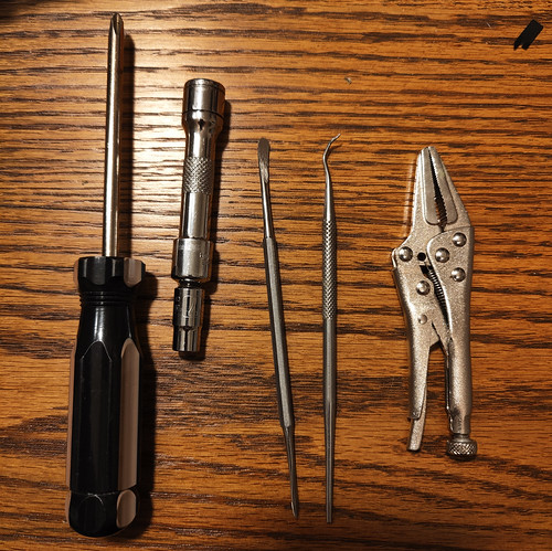
The Usual Suspects


Replacing the Capacitors
With the front panel board out, I used these stainless steel desoldering tubes to isolate the old capacitor legs from the solder. Once both were done, the desoldering tubs would slide through the circuit board to the base of each capacitor. Once done, I wiggled the capacitors to break the RTV and remove them. After a quick cleanup with solder wick, I soldered the new ones right in, taking care to keep them snug against the board and polarity correct. At this point I wish I had some electronics RTV to bond them to the PCB, as the old ones did.

Installing the Microcontroller Board into the Front Panel
Place front microcontroller board on front case + display board and align screw holes and plastic standoffs. Once aligned, push the PCB down until the standoffs pop through. Then put in five screws, left bottom, bottom left, right bottom, bottom right, and bottom middle has a green grounding jumper.
On second thought, some of my photos show the grounding jumper connected to the banana jack, and others to the bottom middle screw. I can't recall which was right, hopefully it doesn't matter. I'll double-check continuity next time it is open.
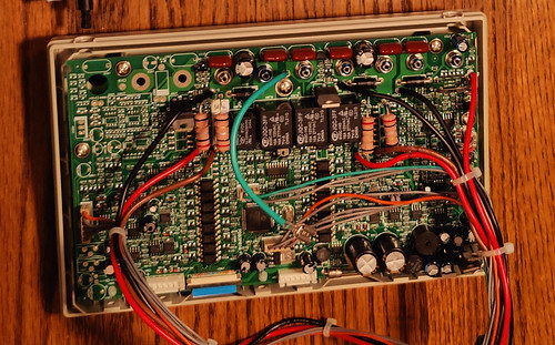
Connect the display flex to J3021
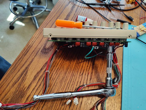
The banana jacks are inserted from the front, then rotated until they align with the transverse test wire holes vertical and they should push through fully. Put a flat washer, split washer, and nut on each. Hand tighten with a 7mm socket. In the above photo, I'm using a thin steel pick inserted into the transverse banana jack hole to keep the jack aligned while I tighten the nut.
Place a small drop of blue lock tite on top of the nut where it meets the threads. Be careful! Don't use too much since it can rot plastic. It really doesn't take much.

Finally, affix the channel 3 knob that fell off during disassembly.
If you have electronics safe RTV, you can put a little at the base of the new caps.
Installing the Front Panel
Align the power button Pusher with the power button hole in the front case and connect the green ground jumper to the Spade terminal on the bottom case. Once done fully slide the front case on the bottom case and install the bottom front pair of screws which are Phillips with a captive flat and split washer. Put the first one in just barely and then put the second in, and then tighten down the first and second just a little.
Wiring the Front Panel
Pull the ch2 harness through the gap between the transformer primary and the channel to transformer connector. Plug it in to j4031 and j4041.

Pull the CH 1/3 harness through the gap between the transformers blue white blue cable just above the relays. Next pass the red and black cable under the thick black brown red orange transformer cable, over and connect it next to j7021 and connect its neighboring 3-pin orange gray gray cable to j7021.
The five pin jst connector goes to the USB breakout PCB. The remaining three cables on the harness are all different sizes and go toward the rear of the bottom PCB and plug into j1041, j1061, j1031.

Finally connect the gray gray blue blue brown brown connector from the transformer to j301 on the front panel.
Install the power button plunger that fell off when you pulled the front panel off the instrument.
Double check that you don't have any loose wires in the previous steps. If you like to live dangerously you might turn it on with the case open but proper electrical safety would tell us that it's best to finish assembling.
Reassembling the Frame and Case
There is an internal retainer bar with two holes at each end and four holes on the top. One end has a pair of threaded holes and the other end has a pair of smooth holes. The smooth holes will go in the back and the end with the threaded holes will slide just under the top of the front case plastics like this. This internal bar will be used to attach the handle later. Put these four screws in and tighten.

Next place the sheet metal case about halfway back over the power supply taking care not to scrape any wires. The end with the screw holes near the top goes toward the back. Slowly slide it forward into the channel around the front case. You should be able to see eight screw holes in total - 3 on each side and two for the handle when it's properly aligned.
Install the three screws on each side using no more Force than necessary. You may need to push or pull on the sheet metal or the front or rear case to get all the holes to line up just right at this stage.
Getting a Handle on Things

For the carrying handle, align the luggage strap then place the two end caps over and finally put in the two screws in the two remaining holes on the top. Note that just outboard of the two screw holes there are two hemispherical detents - the end caps have a little tooth to key them that goes into these detents and needs to be aligned as you tighten the screws. \
Torque It All Down
Finally, locate the front case bottom two screws as well as the left and right panel three screws each, and back all of these out one turn. After that tighten all of them.
Plugging It In
Ensure that the AC selector switches have not been bumped and are in the proper configuration. Snsure that the power switch is in the off position, plug in a power lead, turn it on and give it a try.

In my case replacing these two capacitors has fixed my power supply. The LCD 7 segment digits no longer flicker and the power supply does not reset itself when clicking the relays.
Next I need to verify the rails still track correctly.