WiFi Yagi SWR Shootout
Written 2015-04-19
Tags:Ham Radio WiFi RigExpert HSMM IT-24
The Setup
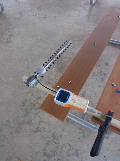
Without an anechoic chamber, I'm a little limited to how I can do my testing. The antenna under test is mounted at the end of a wooden 1x1 beam. The beam is mounted to a picnic table with clamps, holding the antenna 16 inches away from the table and parallel with the table.
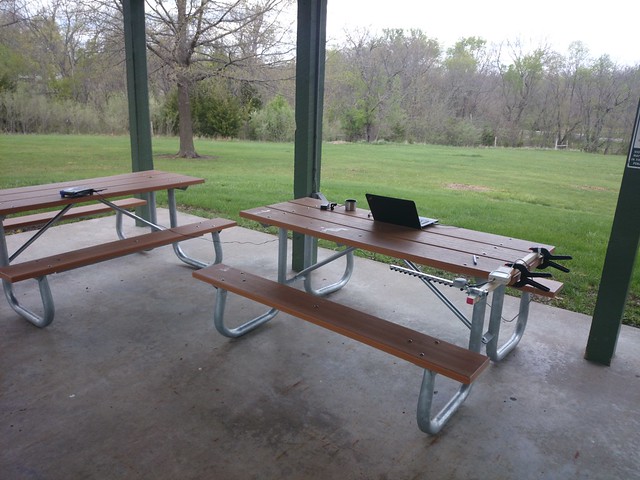
Measurements are provided by my RigExpert IT-24, using the python image scraper I reverse engineered earlier. The self-calibration was executed a few minutes before beginning the test.
The Competitors
I have three styles of antennas, labeled A, B, and C.
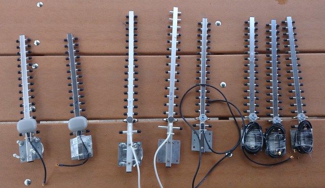
- Type A consists of a short coax pigtail, running into a plastic enclosure with a small metal dipole. I suppose they hoped it would resonate with the other elements on the boom.
- Type B consists of a longer coax pigtail, running into a cylindrical plastic housing, with a loop around the body of the antenna, and some component heat-shrinked inside the loop. My assumption is that whatever components are inside the heatshrink provide an impedance match.
- Type C consists of a longer coax pigtail, running into a cylindrical plastic housing, with a loop around the body of the antenna, but no components under heatshrink.
The SWR
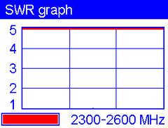
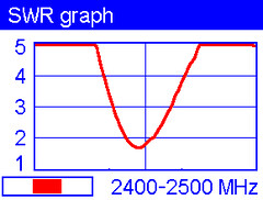
Standing-Wave-Ratio, or SWR, is the ratio of either voltage(VSWR) or power(PSWR) transmitted into an antenna to that emitted. SWR can vary wildly between different frequencies, so the IT-24 includes a feature to plot the SWR of an antenna across a range, specifically between 2.3GHz and 2.6GHz, or some subsets of that range.
High SWR can come from a variety of sources, from bad cables, to poorly designed antennas, to poorly controlled component part tolerances, to a bird nest. Antenna design is a system problem that tends to affect every antenna of that design. Part to part variances tend to indicate production, supply, or quality-control problems. Bird nests will be an ever-present installation location hazard.
Additionally, good SWR can come both from the antenna efficiently transforming electrical signals to radio signals, but it can also come from high-loss cable, where the transmitted power is simply eaten by the cable before it hits the antenna.
| Wide(2.3-2.6) | Narrow(2.4-2.5) | Antenna |
 |
 |
A1 |
 |
 |
A2 |
 |
 |
B1 |
 |
 |
B2 |
 |
 |
C1 |
 |
 |
C2 |
 |
 |
C3 |
 |
 |
C4 |
The Results
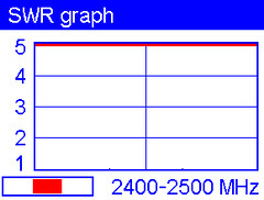
...are surprising. The three designs vary wildly, but none are very stable over frequency.Type A
Ick.
This is just not a good antenna - the SWR meter was pegged, so this antenna will always reflect at least 80 percent of the signal instead of transmitting it to the air. This also means it will receive less than 20 percent of any signal. The IT-24 can measure SWR up to 10:1, but this antenna is so bad I won't even try. I do notice that the coax is secured with a zip-tie, that seems to crush the coax. If there coax were crushed to the point where the shield and center conductor touched, it would certainly return a bad match, but anywhere in-between good coax and crushed coax will likely increase SWR somewhat.
Anyhow, these are garbage and will be discarded.
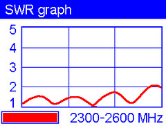
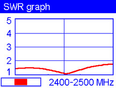
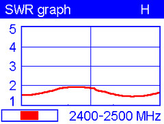
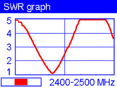
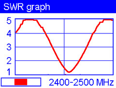
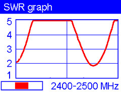
Type B
We have a winner, but I think they could be better.
Antennas B1 and B2 both have 2 to 1 SWR or better across the WiFi range.
However, averaged over frequency, B1 is noticeably better than B2. Good quality antennas will perform similarly in similar circumstances.
Also, the frequencies with low SWR are different between the two samples, which indicates some tolerance or variability in the design, or perhaps in the test.
I am very curious what magic lurks inside the heatshrink, although with only two samples, it is unlikely one will be sacrificed.
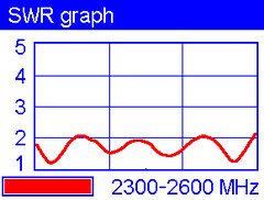
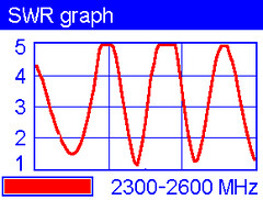
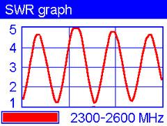
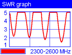
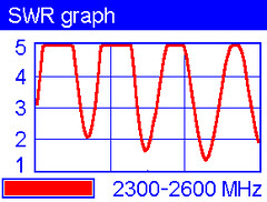
Type C
Welcome to funkytown. These antennas are odd.
First, the cable is 75 ohm, but the IT-24 is a 50 ohm device. It is possible this was a design choice, as 75 ohm cable tends to have lower loss than the equivalent 50 ohm cable, and if the cable is long enough, you can come out ahead by eating a single mismatch loss, but saving on the loss of the cable itself. It is also possible 75 ohm was chosen because it tends to be cheaper.
Next, we see high variance in SWR over frequency. This isn't necessarily bad, as long as the high SWR frequencies are outside of our operating range. But in this case, they do impact the 2.4GHz band.
And, just like the Type B antennas, the variance in SWR is not stable from one antenna to another. But unlike the Type B, where frequency varied SWR between 1 to 1 and 2 to 1, the Type C varies between over 5 to 1 and 1 to 1. This means that each of the four Type C antennas tested will have very different efficiencies on different channels of WiFi.
Conclusions
The three designs tested have very different operating characteristics. Although the eight antennas tested are not enough to be statistically significant, I will likely select Type B for future usage and testing. Type A will be discarded, and Type C may be used based on the channel needed.
Future Work
The next thing to test is how well each antenna can receive signals from a known test transmitter. Since I don't have a calibrated antenna, all tests would be relative to the gain of the antenna used on the transmitter and would have no use outside of comparing the yagis to each other. However, there are storms approaching, so there will not be time to do this test today.