Taking Apart the Honeywell Thermostat
Written 2015-04-27
Tags:Atmel Honeywell KCPL Atmega
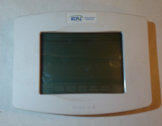
I have a thermostat
It was made by Honeywell, and it came with my house. It is also in daily service without a hot spare, so I have been waiting since last fall to do this teardown.
What is an energy optimizer?
My electricity provider offers a sweet deal where they give you a free programmable thermostat, in exchange for their gentle adjustment of your temperature during peak usage. This implies some sort of communication link between my house and their systems.
What is inside?
One assembled thermostat, front
One assembled thermostat, back
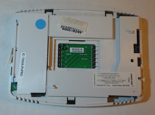
We can see three subsection of the device. In the center is the umbilical to the home. On the left is a small antenna. The rest of the PCB is covered by the frame.
What is under panel number one?
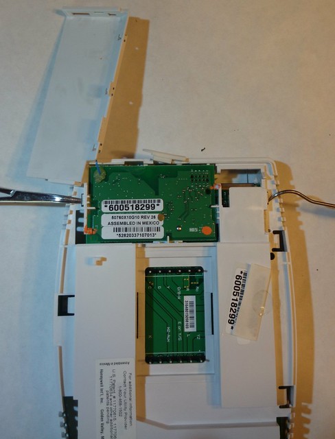
Under a pair of plastic clips we find a small PCB fitted to the main PCB
What could it be?
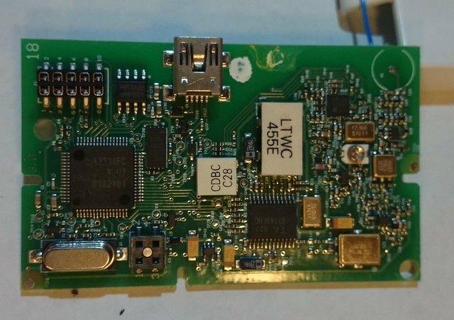
Interestingly, this appears to be the radio section of the device. We find
- at least four crystals or oscillators
- a seemingly unused 10 pin header, possibly for initial programming
- ST M24256 EEPROM
- LTWC455E six-element ceramic filter
- CDBC C28 ceramic discriminator
- 4 pin header going to the main PCB
- USB mini connector although it is not routed for USB
- ta31149 FSK detector
Where does it go?
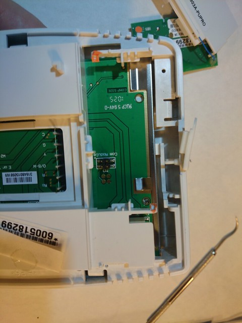
Simple enough. Main PCB micro is Atmega 645v
Seven more clips to go
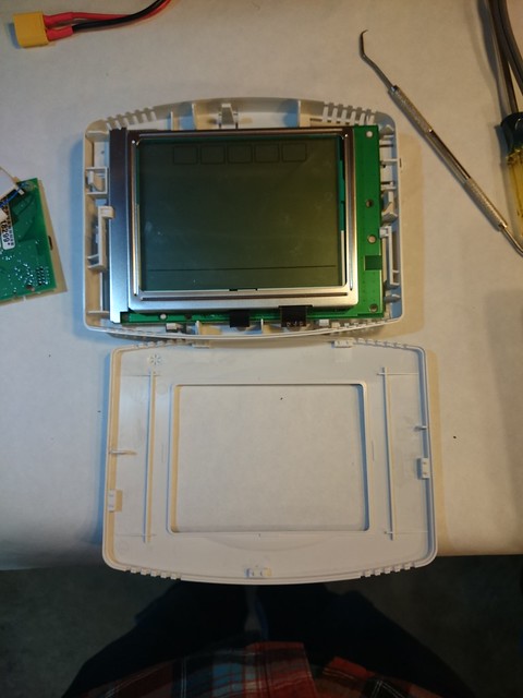
Five clips hold the front bezel on.
Last two clips unclipped
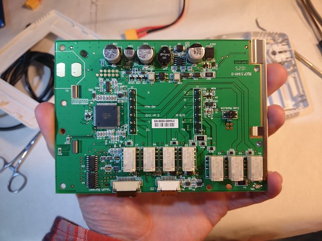
Here is the full rear PCB
Anything under the LCD?
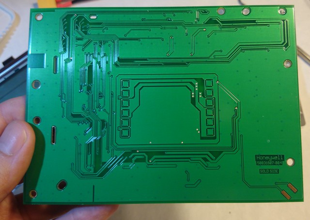
No, not really, just a light-spreader.
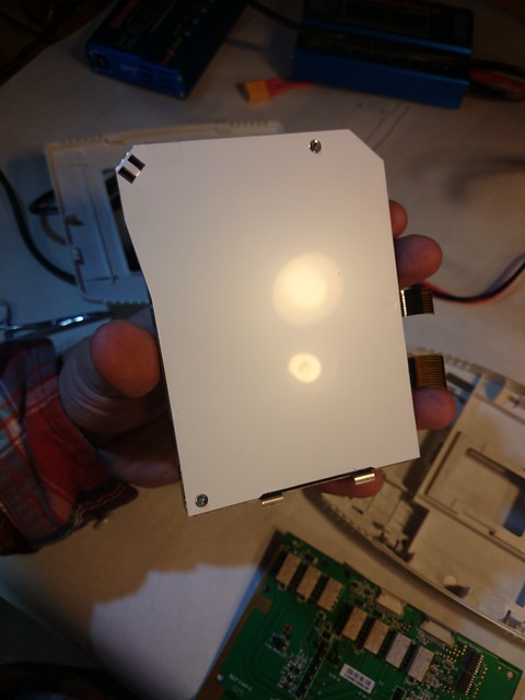
Will it run without the radio?
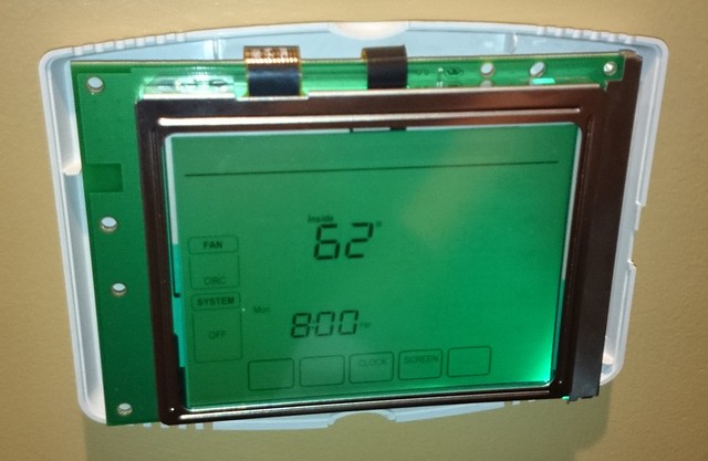
Yes, yes it does.
What is next?
Next would definitely be tracing out the connectors on the radio PCB. Honeywell also makes a WiFi version of this unit, which I suspect is the same but with a different radio PCB. The four-pin connector appears to carry power and ground, leaving two signals for a data bus.