Automatic Video Latency Measurement, Part 1
Written 2022-03-22
Tags:CorrelationCodes Latency BarkerCodes Video Correlation
Problem
I want an automatic method for measuring video latency of a wireless video transmission system. As always, I'm willing to spend far more time automating than it would save one person.
A common current approach is point the wireless camera at a moving target like an analog ticking clock or video of counters or another moving pattern, then use an additional camera to record both the wireless video link display along with the reference target. One of my favorite targets was a chain of indicators on lego gears driven at high speed, each indicator gear reducing the ratio for the next so it had an enormous repeatition interval.
Overall system idea
If we can run some code on the video transmission system, render some images on its display, and analyze frames coming in, we can make the thing measure itself. Once that's measured, we can insert another video link if desired to characterize it.
Video Target Design
To support cameras with auto-exposure and auto-white balance, we need a target with a somewhat stable average brightness and a spread of colors for white-balance.
After a few tries here's what I use:

The inner red/green/blue/grey squares are fixed while the outer corners blink together and edges blink together opposite the corners. In this way, there's always plenty of full brightness and darkness in every frame, and a little color.
Short intro to Barker Coding
Barker codes are short binary(in the sense of two discrete values, -1 and 1, not 0 and 1) patterns of numbers that have a few useful properties:
- The correlation of a Barker code with exactly itself is strong.
- The correlation of a Barker code with a time-shifted copy of itself is weak.
- The correlation of a Barker code with most random signals is also weak.
- The difference between a strong and weak response scales with code length.
This means that if we transmit a Barker code by modulating the display by blinking similarly to programming a Timex Datalink, we can measure when an event occurs by sending out a Barker code then listening for the same Barker code. This general approach of marking a transmission with a correlation code of favorable properties is often used in communications to mark the start of a packet or other timing sensitive information.
Go here to read more: https://en.wikipedia.org/wiki/Barker_code.
Overview
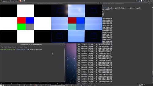
Here's what it looks like - left side is the output target, right side is the camera preview with thin blue alignment rectangles to help you see where to aim it for the corner boxes. Program supports automatic measurements and one-shot(default).
Initial Results
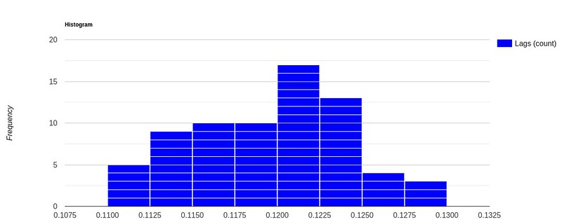
Here's a recording of latency over 71 latency measurements from a 60Hz Thinkpad LCD to a 30Hz PS3 Eye camera. Variation is within 20ms and an input frame is at most 33ms here. Computing at sub-frame offsets in time is the next step for improving this.

Here it is again in a histogram:
Implementation Challenges and Tradeoffs
Operating System Support
Windows has bad OS timing resolution. VSYNC on Linux is hard. I ended up using Linux.
Video Output
Video output seemed straightforward except that at first I used OpenCV which doesn't directly support VSYNC which is needed to measure output FPS, so I ported the video output to OpenGL, then reconfigured my video driver to enable VSYNC, then reconfigured my xserver to enable VSYNC. Year of the Linux desktop and all.
Video Input
Using OpenCV's video stream blocks until a frame is ready, which can often take longer than an output frame depending on input and output frame rates, causes the output stream to fail to draw each frame - this is important for correctly transmitting a code.
The common solution is to use one thread for the camera and one for the display works well, though the startup code is complicated as we use camera resolution to decide display window resolution, and some of the initialization code on each thread seems to cause the other thread to stutter a few frames until we get going - maybe it's Python's GIL?
scan-in/scan-out synchro
When I first got this working with a USB webcam, each run would have different average latency - not wildly different, always within 1 input frame time. I suspect this is due to variation in when the camera starts its scanout vs when the display starts its scan-in. Also, the camera and LCD VSYNCs are not synchronized, so they do tend to drift over time.
Possible Future Improvements
- Sub-frame correlation resolution - currently timing is limited to the slowest frametime
- Live FPS monitoring - currently FPS is computed at startup. If it varies the coding doesn't work well
- Port to OpenHD?
- A more complicated coding scheme could encode a serial number into each pattern for identification later. When using a single Barker code, we have to wait for it to arrive or timeout and retransmit
- Verify any possible off-by-one-frame-time errors. There's a few spots I need to ensure are using the correct start vs end of frame timings.