Rudimentary curve tracing with a programmable power supply
Written 2021-01-18
Introduction
I have a mysterious light-emitting diode I'd like to characterize. The right tool for this job is a curve-tracer, but I don't have one. Curve-tracers work by connecting to a bare component, usually a diode or transistor or other semiconductor, and sweeps across different voltages and plots both the voltage and current through the device caused by the voltage on an XY plot, this is also known as an IV-curve.
What I do have though, is a GW-Instek GPD-3303S programmable power supply with integrated current limiting and readout over USB that is controllable through sigrok.
Can I generate IV curves using sigrok and a power-supply? Kind-of.
Mechanism
A simple approach is to set the voltage limit for the device maximum(power limit for a resistor, forward voltage at max forward current for a diode), set the current limit very low, then for each measurement point:- Wait for the power supply to stabilize and meters to settle
- Read the current and voltage a few times to ensure they have settled
- Increase the current limit slightly
Challenges
Driver
First, I couldn't get sigrok to talk to my supply. This ended up being because I wasn't specifying a baud rate, and sigrok defaulted to a different one than my supply was set to. I patched it to support auto-baud.Current/Voltage sample synchronization
My power supply doesn't support measuring voltage/current at the same time - the sample-rate is quite slow, and since the samples are interleaved we cannot really say that a certain voltage caused a certain current unless we wait long enough after adjusting the supply for everything to settle, which I have done.Polarity
This power supply only supports positive voltages. If I wanted to check reverse biasing I'd have to run it once, swap the leads, run it again, and combine the results.Power supply meter calibration and sensitivity
- Integrated voltmeter resolution is limited to 1mV
- Integrated voltmeter should be accurate within (0.03% of reading + 10mV)
- Integrated ammeter resolution is limited to 1mA
- Integrated ammeter should be accurate within (0.3% of reading + 10mA)
For the parts I want to look at, 10mA is an awful lot of current, but I'm going to do it anyways and see what happens. It's important to recognize that if this 10mA were random(and it could be and the instrument would not be malfunctioning), this experiment would produce completely meaningless results. We could also improve it significantly by programming the power supply and measuring current and voltage with a better mechanism.
Also, I do not know how recently this supply was calibrated. I haven't done it as I haven't been able to find a copy of the service manual. It is important to calibrate power supplier regularly if doing anything like this. For example, when current-limited at 1 to 2 milliamps, the power supply would sometimes current-limit it self with no load. This could be caused by changes in output capacitor equivalent parallel resistance(a leakage path) over time since the last calibration.
Temperature
The IV-relationship of many semiconductor devices varies with temperature. Contemporary curve-tracers can emit a short voltage pulse, conduct their measurement and shut off to cool with a very low duty cycle. Due to the long adjustment time, this isn't really an option - any current through the device under test may impact the measurement.Results:330ohm resistor
I picked this resistor because it can survive some tens of milliamps over several volts and if I made a mistake programming the supply it wouldn't be a big issue. Of note, it is coded as a 5% 330 ohm resistor, through hole, and measures 322 ohms and 323 ohms on my two office multimeters.

Holy error bars batman! What's going on? The error bars displayed are calculated from the formulas in the power supply manual at each data point, which is hopefully a worst-case limit. I suspect the supply is capable of better than this, at least over short ranges like this one, where the samples all agree to with 1 millivolt or 1 milliamp. At least over this short range, it also appears to be monotonic, which will greatly help. It may also help that I'm only measuring at steady-state current and voltage.
Is the measured resistance from curve-tracer wrong? Yes, by about 9%, which is well within the integrated ammeter tolerance at these current ranges.
Is the curve-tracer directionally correct? Also yes, if you ignore the 1mV/1mA quantization errors or look over a large enough area.
Results: Great Big 6A05 Diode
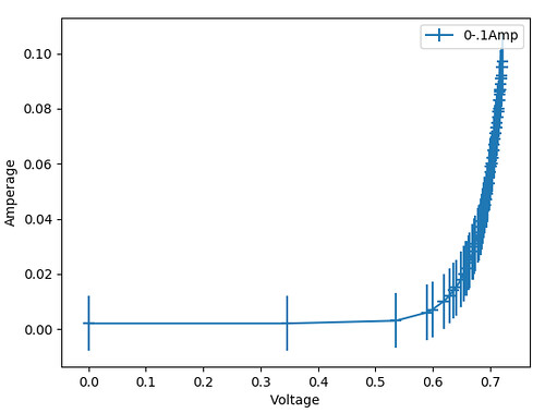
While not the diode I want to characterize, this is a big, resilient, 6 amp diode, again resistant to sofware development errors.Measurement: up to 100 milliamps
This plot shows what we would expect for a diode of this type. It turns on aroud 0.6 volts and is conducting quite a bit of current at 0.7 volts.
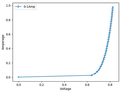
Measurement: up to 1 amp
This is a similar plot with more milliamps per measurement, but up to 1 ampere
Measurement Error
But, when I overlay the above two IV curves from this diode on top of each other, and zoom in some, notice that they do not align well.
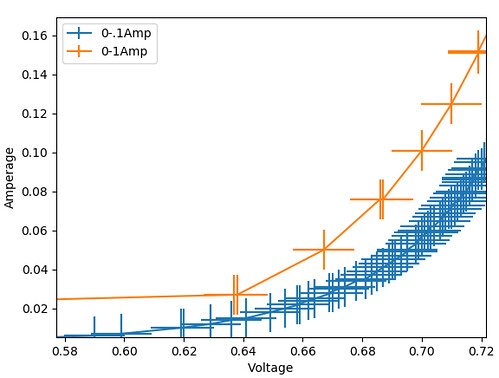
This is likely caused mostly by self-heating inside the diode over time, which will in turn change the IV relationship as the diode temperature changes. How the diode is heating internally has to deal with the currents applied, ambient temperature, location of the test clips on the leads, how long the supply dwelled at each current point, and probably more things, most of which were not controlled, so I wouldn't put much stock into how this two IV-curves differ, just that they do.
It's also possible that the built-in ammeter and voltmeter have some temperature-dependent, voltage-dependent, or current-dependent error, but I don't think it should be too significant at these voltages and currents, according to the manual.
Conclusion
Does it work? It kinda works. It's not great, and I wouldn't rely on it for much other than steady-state operation, which is better measured with a pair of multimeters anyways. You could probably do a lot better with a clock-synchronized triangle wave generator or the actual correct tool for the job.
Was it a fun and engaging Saturday project? Yes.
Does it show expected diode curves? Also yes.
Was it a good introduction to controlling a power supply with sigrok? Yes, that too.
Is it going to be good enough to characterize my mystery diode? Probably not. My mystery LED is likely only capable of 10mA to 15mA maximum, so that's probably not enough points on the current scale to see what I'm looking for. However, if I can measure voltage or current separately, it may work out.