Disassembly of Sherwood Wisdom 2 Dive Computer

Written 2024-04-21

Tags:SCUBA MSP430 

At the spring dive swap meet I picked up a broken Sherwood Wisdom 2 dive computer, just to take apart. I was mostly curious about the mechanical assembly.

A note to anyone considering repairing their dive computer: you should have a manufacturer-trained service center repair it. I bought this planning to destroy it. Here it is, roughly intact, minus compass assembly.

IMG20240421104910

On to the disassembly. I started taking this apart before I photographed it, but I first noticed a small mark of RTV, likely a warranty-void indicator(this photo post cracking it open):

IMG20240421104918

I first was able to lever out the front optical cover.

So, this bezel is important. There were a few slots around the edge of the bezel. In this photo, I have already gotten it mostly loose. I am uncertain how you would take this apart with less damage, likely with a custom tool. The retaining bar the bezel clips over is quite tall, and the bezel plastic brittle, perhaps from age? But anyways, I started at the top with a thin screwdriver, and some guitar picks and spudgers, and worked my way around:

IMG20240421104922

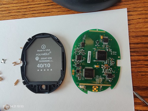
Once that was out of the way, I could remove the gasket and the next layer of display plastic:

IMG20240421104543

At this point, I foolishly pulled the electronics module out by flipping the assembly upside down. This dumped a handful of springs on to my desk, and they bounced away. These things are tiny. I found one in my leg hair. Here are those I was able to find:

IMG20240421111747

Clusters of springs above:

Here is the rear of the circuit board:

IMG20240421105128

And here is the front-side with the LCD unfolded to the left:

IMG20240421105300

Here is the PCB, with better lighting:

IMG20240421110747

Above the left side is mostly analogs for depth sensing. Big IC bottom middle is an LCD controller/driver. Big IC near center is a TI MSP430F148(48KB Flash, 2KB SRAM, 12-bit ADC, UART), with JTAG pins brought out to test points possibly for programming. Top right section is a RS232 line driver for the data port. Bottom right looks like an op-amp for the high-pressure port.

ArduPilot: An Unrelated Matter of Time

Written 2024-03-25

Tags:race-condition ArduPilot 

I found another odd timer behaviour in ArduPilot on Linux, when monitoring the scheduler using a GPIO. I had hooked up a low-priority thread to check in on the autopilot software every second, and if all checks were good, set a pin, delay(1ms), clear pin. The only problem was that rarely, I would find that the pin wasn't going high, but there were no problems recorded.

Historically, delay(N) on Arduino delayed at least N milliseconds. Practically, I couldn't find anything in ArduPilot that cared about sub-millisecond precision that called delay() - usually the caller wanted a rather long amount of time, or it was used for something like throttling logging code. On the Linux scheduler backend, there was a rare race-condition when calling delay(N) just at the top of millisecond. Unknowingly my test setup was configured to expose this discrepancy a couple times per day. Here's the offending code:

void Scheduler::delay(uint16_t ms)
{
    if (_stopped_clock_usec) {
        return;
    }

    uint64_t start = AP_HAL::millis64();

    //Race condition occurs between previous and next calls to millis64()

    while ((AP_HAL::millis64() - start) < ms) {
        // this yields the CPU to other apps
        microsleep(1000);
        if (in_main_thread() && _min_delay_cb_ms <= ms) {
            call_delay_cb();
        }
    }
}

Instead of a ~1ms pulse at 1Hz, a few times per day I would see a dropped pulse. At first, this appeared as a slight deviation in the frequency, as my frequency counter averages pulse-count over measurement period. Until I started looking with an oscilloscope, then I noticed that what I was seeing was a runt pulse, where the GPIO was being cleared low just as soon as it was being set high. With the frequency counter's low-pass filter enabled, these runt pulses were being skipped.

The bug was simple once I accepted it was actually happening. When calling delay(1) it is rare, but possible to call start = milli64() just on the edge of the next millisecond. When this happens, the loop condition degrades into while(((start + 1) - start) < 1){...}, so the loop exits immediately without calling microsleep() to delay execution.

The fix consists of a few parts. First the exit condition is based on the starting timestamp +1 so we cannot return early. The internal resolution is also increased from milliseconds to microseconds, so that the amount of time lost to round-off is reduced. The final calls to microsleep() is now based on how much time is actually needed relative to the starting timestamp, so most drift is accounted except for the last call to microsleep(). The new delay(N):

void Scheduler::delay(uint16_t ms)
{
    if (_stopped_clock_usec) {
        return;
    }

    if (ms == 0) {
        return;
    }

    uint64_t now = AP_HAL::micros64();
    uint64_t end = now + 1000UL * ms + 1U;
    do {
        // this yields the CPU to other apps
        microsleep(MIN(1000UL, end-now));
        if (in_main_thread() && _min_delay_cb_ms <= ms) {
            call_delay_cb();
        }
        now = AP_HAL::micros64();
    } while (now < end);
}

I measured the impact of this on an otherwise idle CPU core on my Raspberry Pi 4, calling delay(100ms) after usleep(rand()%1000) to ensure the test wasn't getting locked to milliseconds. I used delay(100) because delay(1) 1/20000 times would not have made for as interesting of a graph, though the orignal bimodal distribution below is the same cause:

ArduPilotOnLinux delay()

Lauterbach Teardowns

Written 2024-02-27

Tags: Debugging Lauterbach 

I was curious what was inside the Lauterbach debug tips (also called probe heads around here). For the unfamiliar, the Lauterbach power-debug system consists of two parts. The first part is a universal module that connects to a PC over USB or Ethernet, or in the old days parallel. The second part adapts the debug-cable port on the module to a specific JTAG or SWD target, like 20-pin ARM. I took apart two of mine.

LA-7742(ARM9)

I like this one because while Lauterbach generally sticks to a Vintage 1990s hardware design, this LA-7742 seems even older. If you look closely, the housing says W. Germany.

IMG_20240227_194107 IMG20240227195122

This one consists of a 24C02 serial flash and a ALVC164245 level translating tri-state buffer.

IMG_20240227_194128 IMG_20240227_194149

LA-7747(ARM7)

This one looks like the current debug adapter cables, except with a 20pin IDC socket rather than pigtail. even though it is for an older core design than the LA-7742.

IMG20240227194710 IMG_20240227_194801

Inside it appears more complicated, and seems be the same 24C02 serial flash, but instead has MAX4615/6 analog switches, DS90C032 quad differential receivers, and some PACDN006 ESD diode packs.

IMG20240227194333 IMG20240227194225 IMG20240227194435

Older